|
|
Electric Field Transformer |
|
|
Electric Field Transformer |
|
The
electrical concepts behind both the transformer
and the converter is the same; and, are
very basic.
|
|
|
|
This webpage is an extension and an application of the Enigma
of Coulomb's Law.
Arcing completes a circuit -- closes a system -- between two voltage potentials. When arcing occurs, two oppositely charged static voltage potentials can cancel each other out. The arcing problems that occur are usually between two electrically isolated voltage potentials pressures necessary to hold a charge and they are part of the same circuit -- completes a closed system. Anyone or anything that is not part of the closed system can touch an element of that circuit without affect. An example of this is a sparrow on a high voltage power line. A sparrow can sit on a high voltage power line because the sparrow is not part of the circuit. With an eagle or hawk however, it is a different story. It is common for these birds to get 'zapped' when there wings bridge two high voltage power lines. They become a part of the closed system. Some questions raised here are:
The device proposed here is simple. Just as a permanent magnet is to an electret, an electro-magnet is to the device proposed here. |
B
|
 |
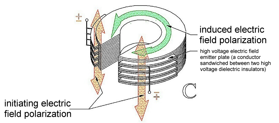 |
| C
Shows a 3 dimensional view of Figure B. This figure shows how the emitters original electrical field polarization tends to be in a different direction (vertically polarized) than the induced electric field in the curved conductive core (toroidally polarized). What this means is; elements of the induced electric field is cross polarized -- 90 degrees -- from the induction electric field. |
| D
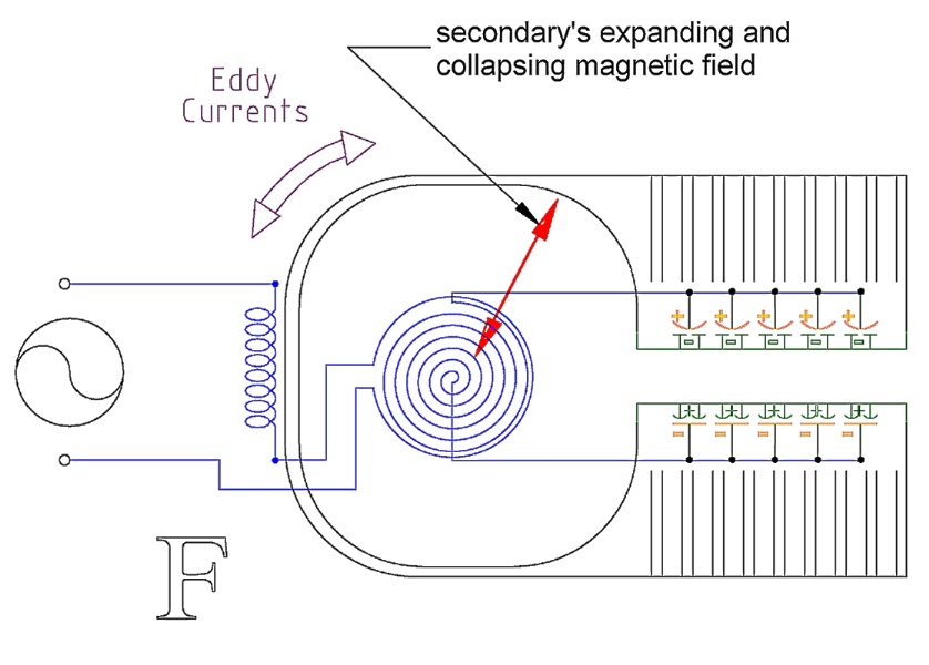
An illustration of an AC transformer using the example of Figures B and C with a high voltage Tesla wound coil (a secondary coil) in the center of a conductive curve mass. A primary coil not only winds around the high voltage secondary coil -- Tesla coil -- in this picture it winds around the conductive core as well. This would only be done if the conductor is a ferrous material. In this case, part of the primary coil would not be directly magnetically inductively coupled to the secondary. The magnetic field generating element of the primary coil has no magnetic effect on the secondary. Only the primary's few turns around the secondary excites the secondary. Figure D illustrates a quarter AC cycle with the high voltage coil's expanding magnetic field with the direction of the field's induced current flow potential in the curved conductor eddy current potential direction. This particular flow direction is in opposition to the electrically induced electron migration direction created by the high voltage emitters -- induced charge migration caused by the charging emitters. |
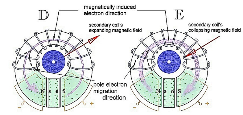 |
| E
The same as Figure D but showing the high voltage coil's collapsing magnetic field with its accompanying eddy current flow potential. This figure shows how this particular eddy current flow potential would compliment electron flow of the induced charge accumulation as the optional power supply -- battery -- does in Figure B (3). (See: This May Be Important) |
| F
An example of an AC circuit schematic for Figures D & E. |
 |
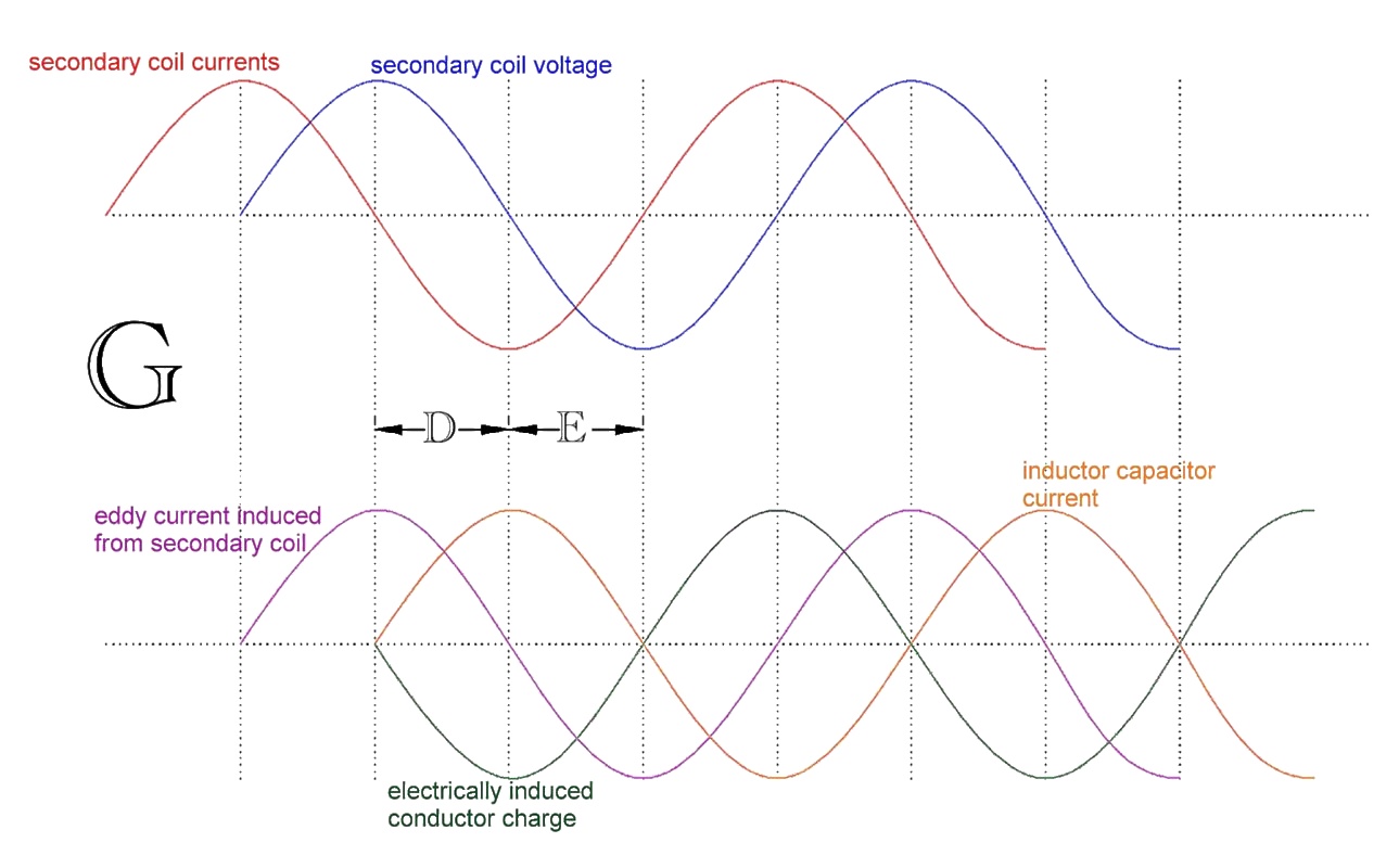 |
| G
A comparison of the various components current phase relationships involved with Figures D & E condition. |
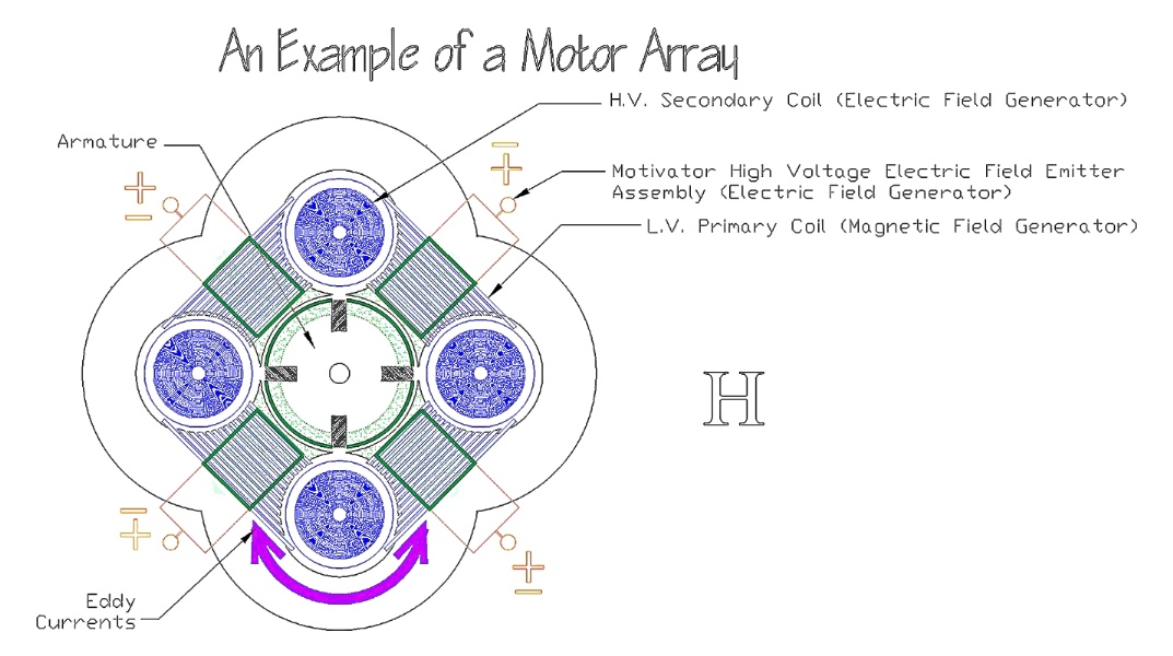
| H
An electric motor -- a practical application -- using magnetic and electric fields comprised of four of these transducer -- electric field isolation transformer -- elements |
 |
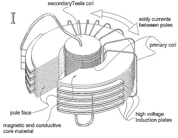
| I
A three dimensional view of a single electric field isolation transformer/capacitor element. |
 |
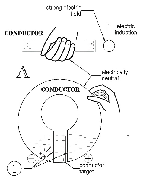
| A
non
ionized atom is electrically neutral. The effects of the positive
and negative fields outside of the atom cancel themselves out from the
reference of the outside at a distance. Normally the same thing occurs
when an electrical charge is placed inside conductive material.
A water molecule is a stable molecule and is electrically neutral. And...the water molecule exhibits highly electrically polarized qualities. This electrical polarization that water has can affect other atoms and molecules around it. This electrical polarization is what makes distilled water the universal solvent and distilled water the perfect dielectric insulator. (Distilled water can't be used as a dielectric insulator for too long because it is the universal solvent. Eventually, distilled water will dissolve part of whatever container you put it in and then it stops being distilled water; it conducts.) What follows is the author's clumsy attempt to get a conductor to exhibit electrically polarized qualities like a water molecule so that the forces present in Coulomb's Law can be used in a high power application.
Electric field induction is like magnetic field induction. When you
place a north pole of a magnet next to a piece of iron, the field of that
magnet induces an opposite field in the iron. The north pole in that
magnet induces a south pole in the iron. And consequently, they attract
each other.
If opposite charges of the same circuit are buried in the opposite ends
-- as opposed to being induced from the outside -- of that electrically
neutral conductor, then that conductor may appear (from the outside) as
being electrically polarized, although it is electrically neutral -- a
closed system like the water molecule.
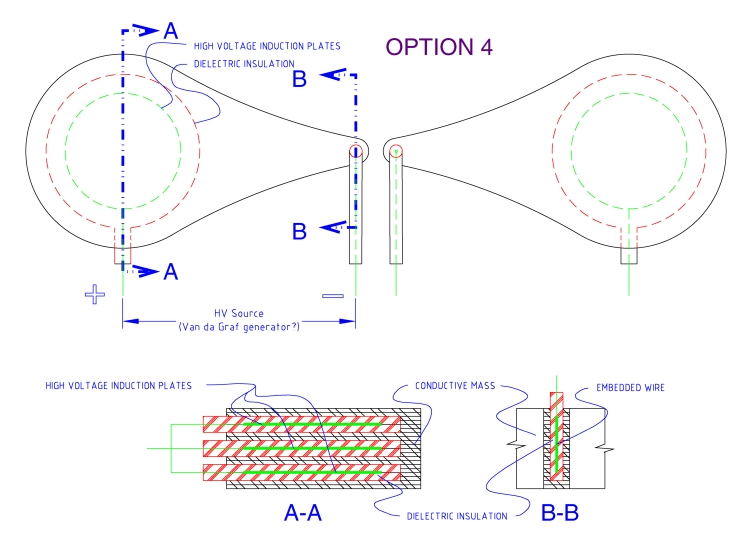
Figure
B and C shows this buried inducing high
voltage charge being placed in the electrically neutral conductor by a
series of parallel 'emitters', each 'emitter' is a conductor laminated
between two high voltage dielectric insulators. These dielectric
insulated emitters would allow electric field passage without any electron
flow.
If the emitters in Figure B and C
are charged with 100,000 to a million volts (like from a Van de Graaf generator)
and be dielectrically insulated from the electrically neutral conductor.
This should induce a fairly strong electric field in the electrically neutral
conductor. The idea is that, from the outside, the core material
exhibits electrically polarized qualities; creating an electric magnet.
One that would tend not to arc to the outside because the charges within
the poles tend to lock the charges on the poles -- be a closed system.1
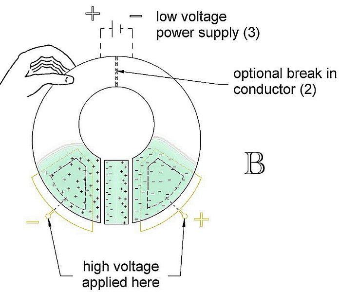
Please Note: In the second case with the insertion of a low voltage power supply -- battery, this device is now a high voltage variable capacitor. It is an electrical device whose high voltage charge holding capability is in relationship to the low voltage applied to the 'poles' and/or target position.
Now, let us kick it up a notch and look at an AC condition. Figures
A, B, and C help
illustrate a static DC condition. To reach a static DC
high voltage condition can be somewhat mechanically cumbersome. With
AC
however, it is very easy using coils. Tesla coils can go to millions
of volts. The spark coil in a car produces around 60,000 volts.
What Figures D, E,
F,
and I are trying to illustrate is a coil/capacitor
combination involving a primary and secondary coil with the secondary coil
providing a high voltage that is supplied to the emitters (a buried capacitor
array) as in Figure F.
As the emitters are switching electrical polarity, there will be migrating
electron travel between the poles. Because of the spatial arrangement
of the electrically neutral conductive core and the Tesla coil, this electron
migration is magnetically coupled to the Tesla coil.
|
||||||
|
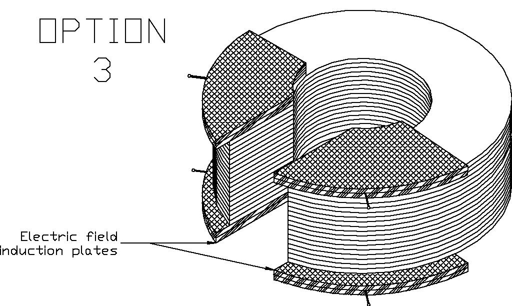
Option
1 (as shown in drawings)
The difference in the two arrangements are:
To physically locate the Tesla coil somewhere else and in its place put a third coil -- an eddy current drive coil. This coil would be driven by some kind of phase control device: capacitance, resistive capacitance, solid state, etc. The purpose of this third coil is to create expanding and contracting magnetic fields that are in a desired phase with the electron migration induced by the high voltage emitters within the core material -- in a complimentary phase with the charging capacitor. This would mean that this coil could be 90 degrees out of phase with the Tesla coil and would need some kind of phase control. Unlike Option 1, this coil's function can go in multiple directions according to the phase control. The two extremes are:
Option 5(not
shown)
|
||||||
| Either way -- AC/DC,
it would be interesting to see the effect when the charge induction plates
start at about 100,000 volts and approach a 1,000,000 volts.
It is recognized that the ideas presented here can be a subject of experimentation in a multitude of directions. All high voltage insulation considerations should be taken into account. The entire high voltage electric field isolation transformer/capacitor assembly (except for the pole surfaces) should be embedded in a high voltage non dielectric insulation material.
In Figure H, four transformer/capacitor elements
are shown arrayed like an electric motor. The motor would act as
an induction motor with electric fields being induced on the armature as
well as the normal magnetic field of an induction motor. For this
motor to have significant power the eddy currents -- charge migration --
would probably be measured in the milliampere range or just above.
Interesting Note: A magnetic induction motor's RPM is due to the frequency of the energizing current. In addition, when a magnetic induction motor armature slows down it creates a greater current flow in the stator coil. This increase in the stator coil -- primary current -- would create an increase in the secondary's high voltage output -- storing more charge -- creating more force. This would compensate the armature slowing with an increased electric field voltage. Unknowns
"Knock yourself out." I do not have anywhere near the resources (intellectual, physical. or fiscal) to begin such a project.
Included with this page is a copy of the aborted patent application for
this device. I screwed up on getting the claims right and this is
a copy of the last try at the transducer.
You may notice that this device is very simple. Because this device
is so simple, it is the author's opinion that it if it works (as the author
guesses), it should have been invented 80 years ago. One person capable
of this, at that time, would have been Nikoli Tesla.
|